Quick facts
Open source GPL2 firmwareUSB 2.0 full speed
HID class
Works on 18F2550, 2450, 2455, 2553, 4450, 4455, 4550, 4553
C code, to be compiled with MCC18 (evaluation version also)
No need for drivers
Communication example for Windows and Linux
No need for DDK or proprietary libraries
Linux version uses hiddev, the native HID manager
Introduction
This guide is not meant to be complete in any way. The purpose is to present and document a quick example of how to implement an USB device using a PIC18 microcontroller, on both firmware and software side.For more detailed info I suggest to read the resources section.
The USB interface has been around for many years, but only recently it has become common in the low cost microcontroller world.
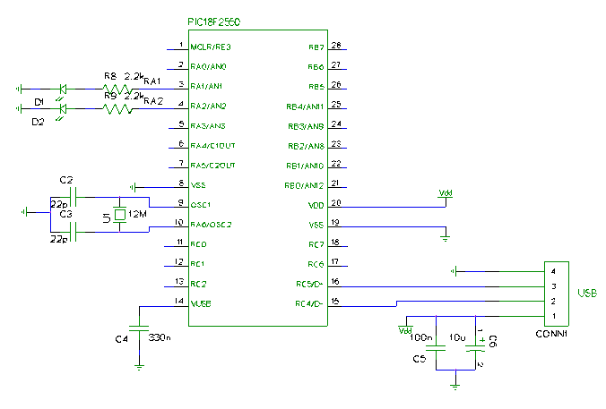
It is now very easy to set up a USB peripheral with a PIC18, as shown in the following diagram (LEDs only show the state of connection):
Unlike serial and parallel interfaces, USB needs a complicated enumeration process in order establish a communication channel.
The so called USB frameworks are code libraries that hide the details of the protocol, so that is possible to use the interface very quickly to communicate with a PC.
One of the most used comes from Microchip, but has a closed license and a somewhat complicated structure; in addition to it more or less all the compiler vendors give a framework with their highly priced products.
On the open source front there are examples of generic USB frameworks, but here I want to document a project that is virtually unknown and hard to find, that also implements the HID class.
The author is Alexander Enzmann; he released his work in 2005 with the periodical Nuts&Volts, but has not really documented or promoted his wonderful project.
I discovered this firmware only recently, and have converted all my projects to use it (see my USB programmer).
Some changes were required to compile with MCC18; it originally required SDCC.
The HID class
The USB protocol divides all peripherals in different classes, according to data transfer requirements and limitations; it is even possible to specifiy a new class, but using a standard one has the advantage that all major operating systems already include the proper software driver.In particular the HID class (Human Interface Device), which comprises keyboards and mice, is perfect for interfacing small microcontrollers: data is generally exchanged using interrupt transfers with a maximum of 64 bytes per packet and a maximum speed of 64 KB/s.
During enumeration of HID devices the system reads a data structure called HID report descriptor, which specifies how many bytes to transfer and how to interpret the data.
This method is very flexible and allows to define all types of devices, for example a keyboard with extra keys or with integrated pointer, and in general any combination that would not be explicitly described in an operating system.
For more information see the specification of HID class.
However, in electronics projects we are often not interested in describing to the system what single bits or bytes mean; if we only care about transferring data the report descriptor will only specifiy the packet size.
Data is exchanged by means of an output report and an input report, with direction respectively from and to the PC; it is also possible to use a feature report in both directions.
Configuring and using the firmware
The first thing to do is to install MPLAB and MCC18 (the trial version is fine); dowload both from the Microchip website.Here I put an example of application; it includes C source files and an MPLAB project.
The resulting device uses the first byte of the incoming packet to control port B (PORTB<7:2>); RB1 and RB0 indicate the transfer method used:
01 = output report via interrupt,
10 = feature report,
11 = output report via control endpoint.
The response is composed by:
the state of port A (1 byte);
the transfer type, 0xF0 if interrupt, 0xF1 if feature, 0xF2 if control;
a 2 byte timestamp incremented every 10.93 ms;
the remaining bytes received.
The source file usb.c contains the data structures that identify the peripheral; the first to be read is the device descriptor:
	rom byte deviceDescriptor[] =
	{
		0x12, 0x01, // bLength, bDescriptorType
		0x00, 0x02, // bcdUSB (low byte), bcdUSB (high byte)
		0x00, 0x00, // bDeviceClass, bDeviceSubClass
		0x00, E0SZ, // bDeviceProtocl, bMaxPacketSize
		0xD8, 0x04, // idVendor (low byte), idVendor (high byte)
		0xFF, 0x01, // idProduct (low byte), idProduct (high byte)
		0x01, 0x00, // bcdDevice (low byte), bcdDevice (high byte)
		0x01, 0x02, // iManufacturer, iProduct
		0x00, 0x01  // iSerialNumber (none), bNumConfigurations
	};
Vid and Pid are usually assigned by the USB consortium under payment, but of course for non commercial projects
it's possible to use any number, for example 4D8 1FF; 0x4D8 is the Microchip ID.The report descriptor specifies a 64 bytes report with reserved application; this means that the system won't attempt to decode and use it, as it would with keyboards and mice; the feature report is also 64 bytes long:
	rom byte HIDReport[HID_REPORT_SIZE] = {
		0x06, 0xa0, 0xff, 	// USAGE_PAGE (Vendor Defined Page 1)
		0x09, 0x01,       	// USAGE (Vendor Usage 1)
		0xa1, 0x01,       	// COLLECTION (Application)

		// The Input report
		0x09, 0x03,     	// Usage ID - vendor defined
		0x15, 0x00,     	// Logical Minimum (0)
		0x26, 0xFF, 0x00, 	// Logical Maximum (255)
		0x75, 0x08,     	// Report Size (8 bits)
		0x95, 0x40,     	// Report Count (64 fields)
		0x81, 0x02,     	// Input (Data, Variable, Absolute)

		// The Output report
		0x09, 0x04,     	// Usage ID - vendor defined
		0x15, 0x00,     	// Logical Minimum (0)
		0x26, 0xFF, 0x00, 	// Logical Maximum (255)
		0x75, 0x08,     	// Report Size (8 bits)
		0x95, 0x40,     	// Report Count (64 fields)
		0x91, 0x02,      	// Output (Data, Variable, Absolute)

		// The Feature report
		0x09, 0x01,     	// Usage ID - vendor defined
		0x15, 0x00,     	// Logical Minimum (0)
		0x26, 0xFF, 0x00, 	// Logical Maximum (255)
		0x75, 0x08,     	// Report Size (8 bits)
		0x95, 0x40,     	// Report Count (64 fields)
		0xB1, 0x02,      	// Feature (Data, Variable, Absolute)

		0xc0              	// END_COLLECTION
	};
The difference between input/output report and feature report is that the former uses generally an
interrupt transfer (64KB/s max) to endpoint 1, the latter always a control transfer to
endpoint 0, which is shared with the standard USB message flow; in this case, unlike interrupt transfers, the
operating system does not guarantee a maximum latency but balances the data flow as it thinks is better;
transfers are split in packets of bMaxPacketSize0, which is specified in the device descriptor;
in usb.h it is defined as E0SZ.The feature report was conceived to sporadically transfer configuration options or attributes to other data (for example the state of keyboard LEDs); input/output reports would carry the real data; it is however up to the designer to choose which one(s) to use.
If there's no need for a feature report it's possible to delete the corresponding section from the report descriptor; also delete HIDFeatureBuffer[HID_FEATURE_REPORT_BYTES] and functions SetupFeatureReport(byte reportID), SetFeatureReport(byte reportID), and GetFeatureReport(byte reportID); finally delete the calls to those functions in ProcessControlTransfer(void) and ProcessHIDRequest(void)
Another way to access input/output reports is using HID messages GET_REPORT and SET_REPORT directed to endpoint 0 (control mode); it is similar to the feature report transfer, and the same considerations made before apply here as well; however the operating system documentation advises to use interrupt mode for continuous transfers.
If there's no need to use GET_REPORT and SET_REPORT it's possible to delete functions SetupOutputReport(byte reportID), SetOutputReport(byte reportID), and GetInputReport(byte reportID); also delete calls in ProcessControlTransfer(void) and ProcessHIDRequest(void).
Back to the configuration, string descriptors are read by the system to give a textual description of vendor and product; they must be 2 byte unicode as the following example:
	rom byte stringDescriptor1[] =
	{
	    18, STRING_DESCRIPTOR, // bLength, bDscType
	    'S',0,'t',0,'r',0,'i',0,'n',0,'g',0,' ',0,'1',0,
	};
In usb.h is specified the size of data reports; these must of course match what is written in the report descriptor:
#define HID_INPUT_REPORT_BYTES   64
#define HID_OUTPUT_REPORT_BYTES  64
#define HID_FEATURE_REPORT_BYTES 64
USB communication routines are implemented without interrupts; this is possible because the protocol specifies very long response times (after enumeration there's a 5 second limit for data transfers) and the USB peripheral keeps sending NAck packets automatically if new data is not available.
The advantage is that user functions can take full control of the microcontroller.
The main cycle repeatedly calls the USB transaction manager and the user function ProcessIO():
	while(1){
		EnableUSBModule();
		if(UCFGbits.UTEYE != 1) ProcessUSBTransactions();
		ProcessIO();
	}
Evidently ProcessUSBTransactions() handles the protocol, i.e. what comes to endpoint 0.What is interesting to the user is how to send and receive data; input and output reports are transferred to endpoint1 buffers (HIDRxBuffer and HIDTxBuffer, in USB RAM), and from there they must be copied to a user location by calling the reading function:
number_of_bytes_read = HIDRxReport(receive_buffer, HID_OUTPUT_REPORT_BYTES);Reading data empties the input buffer and allows the device to receive a new report; up to that point all incoming data is not accepted.
Here is the corresponding write:
number_of_bytes_written = HIDTxReport(transmit_buffer, HID_INPUT_REPORT_BYTES);When using GET_REPORT and SET_REPORT it's necessary to insert user code in functions SetOutputReport(byte reportID) and GetInputReport(byte reportID).
So with interrupt transfers the user code must check if something was received; with control transfers it is the protocol handling routine that calls the user function whenever a transfer is complete.
Regarding the feature report, the procedure is similar to that described above, only change functions: SetFeatureReport(byte reportID) and GetFeatureReport(byte reportID).
How to compile
This MPLAB project uses the MCC18 compiler, but probably the executable path will be different; the first time you compile MPLAB will report this and will allow to use the right paths.It's also necessary to change the library path: from project options, section directories, click on suite defaults or set paths manually.
If you want to change device (presently is 18F2550), go to Configure->Select Device.
It will be necessary to change configuration bits accordingly, and to specify a new linker script; default scripts are ok, except for devices with less RAM, as 18F2450 and 4450: here you need to reduce stack size to something like 40 bytes.
The quartz oscillator can run at any multiple of 4 MHz, as long as the input divider is set accordingly; now it runs at 12 MHz.
How to simulate
MPSIM does not presently support USB peripherals, but anyways it wouldn't be useful to simulate the enumeration process; what is important is to check the code that uses the transferred data.It can be done as follows:
add a breakpoint on the line
if((deviceState < CONFIGURED)||(UCONbits.SUSPND==1)) return;execute (Run, F9, or go button);
from File registers or Watch window change the value of deviceState to 5 (which corresponds to CONFIGURED state).
This way you skip enumeration; now you have to stop after function HIDRxReport and change the number of bytes read (number_of_bytes_read variable).
Transferred data should be written manually on HIDrxBuffer.
From now on it's like a regular debugging session.
To simulate transmission is sufficient to change number_of_bytes_written, if used.
Communication with PC
Communication code depends from the operating system; it is generally possible to use all-in-one libraries that take care of device detection and communication, but I prefer not to depend from external packages (which carry their own licensing problems) and to use the operating system directly.Windows
My C example (compiled with DevC++) is a command line program that sends and receives a 64 byte packet using various methods.To avoid using the DDK (driver development kit) I link explicitly the system libraries needed, hid.dll and setupapi.dll, and load manually the functions needed.
The program scans all HID devices until it finds one with the correct vid&pid.
There are 3 methods to exchange data: with input/output report in interrupt mode, in control mode, or with a feature report.
The firmware must of course support the method you choose.
Microsoft advises to use interrupt mode for continuous transfers; in this case the functions are similar to file I/O:
Result=WriteFile(WriteHandle,bufferU,DIMBUF,&BytesWritten,NULL);to write, and
	Result = ReadFile(ReadHandle,bufferI,DIMBUF,&NumberOfBytesRead,(LPOVERLAPPED) &HIDOverlapped);
	Result = WaitForSingleObject(hEventObject,10);
	ResetEvent(hEventObject);
to read.
This is an asynchronous read, i.e. ReadFile returns immediately and you have to call WaitForSingleObject to wait for I/O completion.
Communication in control mode (through SET_REPORT and GET_REPORT) can be commanded with:
HidD_SetOutputReport(DeviceHandle,bufferOut,n)to write, and
HidD_GetOutputReport(DeviceHandle,bufferIn,n)to read.
Similarly to use the feature report:
HidD_SetFeature(DeviceHandle,bufferOut,n)to write, and
HidD_GetFeature(DeviceHandle,bufferIn,n)to read.
In all these cases the first byte transferred indicates the report ID (usually 0); other data follows, so the total size increases by one (here 65 byte).
If you request less data than specified in the report descriptor the system reports an error; if you request more the response is padded with zeroes.
See actual code for details.
HidCom options:
-h, --help     	 help
-c, --control    use control transfer [no]\
-d, --delay    	 read delay (ms) [0]
-f, --feature  	 use feature report [no]
-i, --info     	 device info [no]
-I, --increment	 increment byte 6 every transfer [no]\
-p, --pid      	 Product ID [0x1FF]
-q, --quiet    	 print response only [no]
-r, --repeat   	 repeat N times [1]
-s, --size     	 report size [64]
-v, --vid      	 Vendor ID [0x4D8]
Example:
HidCom -i -r 5 -d 16 1 2 3 4 5 6 7 8 9 a b c d e f 0
Linux
Of all possible methods to communicate with HID devices I use what is probably the lowest level: interacting with hiddev, the Linux HID driver; in this way there's no need for external libraries.After plugging an HID peripheral the operating system creates a device /dev/usb/hiddevX, where X is a progressive number.
You need reading rights to communicate with it:
>sudo chmod a+r /dev/usb/hiddev0To permanently enable a user do the following (on Ubuntu and other Debian based distributions, check for others):
as root create a file /etc/udev/rules.d/99-hiddev.rules
if you want to enable a user group write:
KERNEL=="hiddev[0-9]", SUBSYSTEM=="usb", SYSFS{idProduct}=="01ff", SYSFS{idVendor}=="04d8", GROUP="<group>"
where <group> is one of the user groups (to get a list type "groups");
select a suitable group and if your user desn't belong to it execute "addgroup <user> <group>".Or, if you want to enable all users, change reading permissions:
KERNEL=="hiddev[0-9]", SUBSYSTEM=="usb", SYSFS{idProduct}=="01ff", SYSFS{idVendor}=="04d8", MODE="0664"
restart udev to apply changes:
>/etc/init.d/udev reloadPid and vid come from the example firmware, change them according to what is in the device.
The program communicates using ioctl calls, passing as parameter some data srutctures that specify the transfer mode.
	struct hiddev_report_info rep_info_i,rep_info_u;
	struct hiddev_usage_ref_multi ref_multi_i,ref_multi_u;
Hiddev was developed for classic input/output devices, so has many functions to check the single usages specified in the report descriptor; however we need a way to transfer the whole report in one time; this is possible with HIDIOCSUSAGES and HIDIOCGUSAGES; data is in ref_multi_u.values and ref_multi_i.values.
Interrupt transfer:
	ioctl(fd,HIDIOCSUSAGES, &ref_multi_u); //Write ref_multi_u.values
	ioctl(fd,HIDIOCSREPORT, &rep_info_u);
	...
	ioctl(fd,HIDIOCGUSAGES, &ref_multi_i); //Read to ref_multi_i.values
	ioctl(fd,HIDIOCGREPORT, &rep_info_i);
Control transfer:
	ioctl(fd,HIDIOCSUSAGES, &ref_multi_u); //Write ref_multi_u.values
	ioctl(fd,HIDIOCSREPORT, &rep_info_u);
	...
	ioctl(fd,HIDIOCGREPORT, &rep_info_i);
	ioctl(fd,HIDIOCGUSAGES, &ref_multi_i); //Read to ref_multi_i.values
In reality only reads are forced to control endpoint; I couldn't find a way to force writes.
Anyways there's no reason to choose control transfers when interrupt is available; and if a device doesn't support interrupt it is not given to hiddev.
Transfer using the feature report (after specifying HID_REPORT_TYPE_FEATURE in the data structures):
	ioctl(fd,HIDIOCSUSAGES, &ref_multi_u); //Write ref_multi_u.values
	ioctl(fd,HIDIOCSREPORT, &rep_info_u);
	...
	ioctl(fd,HIDIOCGREPORT, &rep_info_i);
	ioctl(fd,HIDIOCGUSAGES, &ref_multi_i); //Read to ref_multi_i.values
See actual code for details.
HidCom options:
-h, --help     	 help
-c, --control    use control transfer [no]\
-d, --delay    	 read delay (ms) [0]
-f, --feature  	 use feature report [no]
-i, --info     	 device info [no]
-I, --increment	 increment byte 6 every transfer [no]\
--path           device path [/dev/usb/hiddev0]\
-p, --pid      	 Product ID [0x1FF]
-q, --quiet    	 print response only [no]
-r, --repeat   	 repeat N times [1]
-s, --size     	 report size [64]
-v, --vid      	 Vendor ID [0x4D8]
Example:
HidCom -i -r 5 -I 16 1 2 3 4 5 6 7 8 9 a b c d e f 0
Downloads
Firmware: complete MPLAB project or compiled firmware for 18F2550 (.hex)HidCom for Linux
HidCom for Windows
Links
DevC++USB 2.0 standard
HID page on USB.org
USB Central
USB & PIC
Microchip
hiddev documentation
GNU/GPL
Contacts
For informations or comments:Alberto Maccioni